ESP32 - building an air-quality monitor with a coding agent
2026-09-28
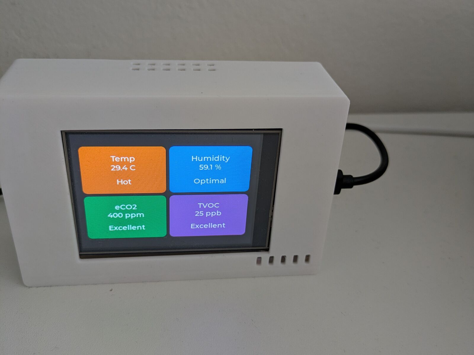
I bought an ESP32 board with a built-in display from AliExpress. It's an ESP32-32E with a 3.2" 240x320 IPS touchscreen, the datasheet calls it E32R32P. I wanted to turn it into a small air-quality monitor for my desk.
Getting it running was super complicated. All I got was a couple of example files and a pretty obscure datasheet. The demo worked, but after that I hit a lot of issues with compilation, deploying to the board, configuring the pins and getting everything set up correctly. For a while the backlight was on but the screen stayed black, which turned out to be the wrong SPI mode.
With the help of a coding agent I got through it. Without it I would have struggled a lot, because I'm not that experienced in the hardware ecosystem, and it's really bad compared to the software one. Working through the build errors, flashing and pin config together with the agent felt really cool.
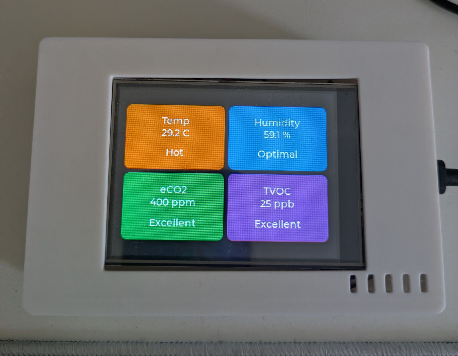
The firmware is ESP-IDF with LVGL for the UI. Every 5 seconds it reads three sensor modules over I2C, averages the last five readings and shows four values as four cards: temperature, humidity, eCO2 and TVOC, each with a simple label like "Optimal" or "Excellent". The gas sensors need time to warm up after power-on, until then the eCO2 and TVOC cards just say "Warming".
Everything is on GitHub: the firmware, the OpenSCAD files and STLs for the enclosure, and a wiring diagram. If you want to build the same thing, start at MQ37/esp32-air-quality-monitor.
A caveat: I cleaned up the code for the public repo, and I'm traveling right now, so I can't flash the board. The cleaned-up version compiles, but it has not been tested on the hardware yet. Usually I flash it over USB-C. I decided to publish it anyway, so if something breaks, tell me.
Enclosure
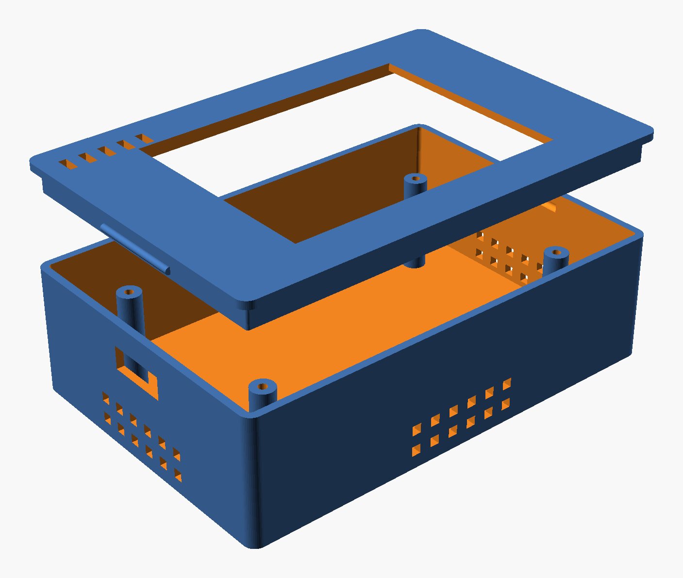
The enclosure is 3D printed and was designed in OpenSCAD by an LLM (I think it was GLM 5.1 or one of the Kimi models, I don't remember exactly). That was really impressive to me even before the Opus 5.5 days, and models are even better at 3D stuff nowadays. I just measured the board and its holes, told the LLM the numbers and it produced a really nice two-piece enclosure.
The base has four standoffs for the board, an opening for the USB-C cable, vent slots low on the walls and space under the board for the sensors. The lid has a window for the display and a few exhaust slots on top, and it snaps into the base, so no screws there. I printed it on a Prusa CORE One in PLA, screwed the board in and it was done.
One problem with this enclosure: it gets hot inside. The ESP32 and the display backlight keep heating the closed box and there is almost no airflow, so the board gets hotter and hotter. The temperature card shows much more than the real room temperature, which makes it not very useful as a thermometer. The next iteration of the enclosure definitely needs more ventilation, so air can actually flow through it.
Soldering
This was also my first time soldering. I bought a Yihua 706+ soldering and hot air station with a set of spare tips, and since I live in a small studio I also got a REFOX DFE-20B desktop fume extractor, so I don't fill the room with fumes. The solder joints are certainly not the prettiest, but they work, and I learned something new, which was cool.
What's inside
To keep it simple: three sensor modules, four values on the screen. This is what I actually bought:
- ESP32-32E (ESP32-WROOM-32) board with a 3.2" ST7789P3 240x320 IPS display and XPT2046 resistive touch, both on SPI
- CJMCU-680 module with a Bosch BME680: gives me the temperature and humidity cards, and I also feed both values to the two gas sensors for compensation. I2C, 0x77
- CCS811 air-quality module: gives me the eCO2 card. I2C, 0x5A
- ENS160 + AHT21 module: gives me the TVOC card. This one is a two-in-one board with two chips on it, an ENS160 (ScioSense, air quality, I2C 0x53) and an AHT21 (temperature and humidity). I only use the ENS160, the firmware doesn't read the AHT21.
So there are three boards, and four chips if you count the AHT21 that I don't use.
Why so many sensors when several of them measure similar things? The CCS811 and the ENS160 both report eCO2 and TVOC, and the BME680 and the AHT21 both measure temperature and humidity. I read online that when a gas sensor is also used for temperature, it gives bad readings on its other values. So instead of figuring out how to work around that, I bought more sensors and gave each one a single job.
What's next
Overall it was a really great experience. Next I'd like to build my own drone from scratch. I already bought a bunch of brushless motors and sensors, so that's my next target once I'm back from SF.